
- When Rigid Waveguides Fall Short
- A Flexible Connection Solution for Industrial Microwave Systems
- Key Microwave Technical Specifications
- Common Field Issues and Solutions
- Selection Decision: When Should Flexible Waveguides Be Used?
- Procurement Considerations
- Importance of Customizing Length and Flange Configuration
- Conclusion
When Rigid Waveguides Fall Short
Component connections in industrial microwave systems do not always follow a straight-line layout. Practical deployments often require flexible connection solutions to accommodate specific lengths or flange configurations.
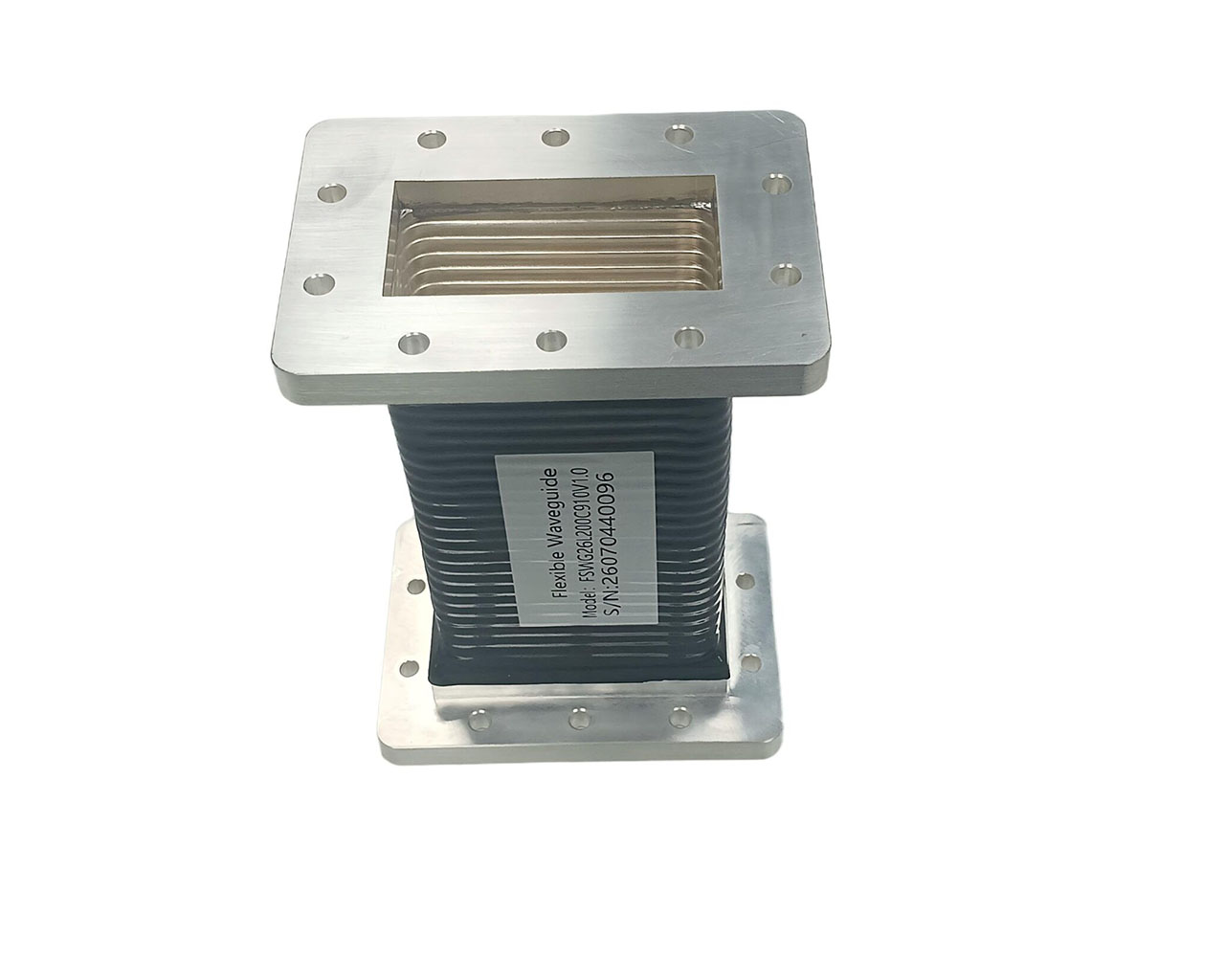
Pindom’s Flexible Waveguide WR340 BJ26 Customizable Flexible Waveguide Connector for Industrial Microwave System is designed specifically for these applications. It is a highly customizable flexible waveguide connector that allows tailored lengths and flange specifications based on customer drawings.
A Flexible Connection Solution for Industrial Microwave Systems
This product is a BJ26-WR340 specification flexible waveguide positioned as a custom-made connection component for industrial microwave systems. Its core design objective is to provide a tailored fit for length and flange configurations, ensuring low microwave loss and stable, reliable signal transmission.
Key Microwave Technical Specifications
- Frequency Range: 2.17–3.30 GHz
- Voltage Standing Wave Ratio (VSWR): ≤1.10
- Insertion Loss: ≤0.15 dB
- Operating Temperature: -55°C to +85°C
- Storage Temperature: -55°C to +85°C
- Flange Types: FDP26, FDM26
- Color: Silver
- Minimum Order Quantity (MOQ): 1 Piece
These parameters form the primary basis for selection. The 2.17–3.30 GHz range must match equipment operational requirements. A VSWR of ≤1.10 and insertion loss of ≤0.15 dB meet baseline system performance standards. The wide operating temperature range of -55°C to +85°C ensures adaptability to harsh environments.
Common Field Issues and Solutions
In industrial microwave projects, the Pindom Flexible Waveguide WR340 BJ26 effectively addresses three major pain points:
Installation difficulties due to limited space
Forcing a rigid waveguide to bend can degrade VSWR (often exceeding 1.5) or crack flanges. The Pindom flexible structure allows axial compression and angular deflection while maintaining a VSWR of ≤1.10. The bending radius must be at least three times the waveguide’s broad-wall dimension to avoid excessive twisting.
Poor contact due to production line vibration
Rigid flanges are prone to loosening and arcing under prolonged vibration. The flexible body absorbs mechanical stress, reduces vibration energy at the flange interface, and maintains impedance continuity. Anti-loosening washers must still be used, and bolts tightened to the torque specified in the IEC 60153 standard.
Connection misalignment due to thermal cycling
Temperature fluctuations induce axial stress in rigid waveguides and cause VSWR drift. The flexible structure compensates for thermal displacement and maintains a stable VSWR of ≤1.10 across the full operating temperature range of -55°C to +85°C. Performance verification under both cold and hot conditions is recommended.
Selection Decision: When Should Flexible Waveguides Be Used?
Scenarios favoring flexible waveguides:
- Installation path involves two or more non-coplanar bends
- Equipment is subject to continuous vibration or shock loads
- Frequent disassembly is required, and space constraints prevent the withdrawal of rigid waveguides
- Retrofitting existing equipment where interface tolerances exceed limits, making rigid waveguide alignment impossible
Scenarios where flexible waveguides should not be used:
- Straight-line paths without vibration (rigid waveguides offer lower cost and lower loss)
- Extremely high power density (e.g., CW >1 kW/cm²; thermal simulation for heat dissipation is required first)
- Frequencies outside the 2.17–3.30 GHz range
Comparison with coaxial cables: In S-band industrial applications, coaxial cables have significantly lower power capacity than WR340 waveguides and exhibit higher high-frequency losses. Consider them as an alternative only when power is <50 W and space is extremely limited.
Procurement Considerations
To ensure the product is ready for use upon arrival, verify the following points before purchasing:
- Verify Minimum Bend Radius: Request data on static and dynamic bend radii. Installing in a space smaller than these limits will drastically reduce mechanical lifespan.
- Check Flanges and Torque: Provide existing equipment flange drawings to verify FDP26/FDM26 hole patterns and sealing grooves. Obtain recommended installation torque. Excessive tightness crushes the flexible body, while insufficient tightness causes leakage.
- Verify Environmental Compatibility: If the site involves corrosive gases, high humidity, or dust, confirm protective specifications such as silver plating thickness. Request salt spray test reports if necessary.
- Confirm VSWR Test Conditions: Do not accept products based solely on data from a straightened state. Require VSWR test reports that simulate the actual bent installation configuration.
- Align MOQ and Lead Times: Pindom’s MOQ is 1 unit, facilitating prototype validation. Project plans must clearly distinguish between sample and batch delivery milestones to avoid delaying the overall system schedule.
Importance of Customizing Length and Flange Configuration
Pindom supports manufacturing entirely according to customer drawings. Designers can determine length and flange configurations during the customization phase. This eliminates the need to select fixed specifications and then reverse-engineer the equipment layout, significantly simplifying the system integration process.
Conclusion
Pindom’s Flexible Waveguide WR340 BJ26 Customizable Flexible Waveguide Connector for Industrial Microwave System is designed specifically for industrial microwave systems. It supports customization of length and flanges based on drawings. With a frequency range of 2.17–3.30 GHz, VSWR ≤1.10, insertion loss ≤0.15 dB, and an operating temperature range of -55°C to +85°C, it effectively resolves field challenges such as space constraints, vibration-induced failure, and thermal expansion mismatches. It provides users with a reliable end-to-end connectivity solution from selection and procurement to installation.